
 jaunumi
I. Radioviļņu pamatīpašības
Paredzamais lasīšanas laiks: 15 minūtes
1.1 Radioviļņu definīcija
Radioviļņi kalpo kā signālu un enerģijas nesēji, ko rada svārstīgu elektrisko un magnētisko lauku savstarpēja sasaiste, ievērojot maiņstrāvas savienojuma likumu "elektrība rada magnētismu, un magnētisms rada elektrību". Izplatīšanās laikā elektriskais un magnētiskais lauks vienmēr ir perpendikulāri viens otram un abi ir perpendikulāri viļņa izplatīšanās virzienam, padarot tos par **šķērsvirziena elektromagnētiskajiem viļņiem (TEM viļņiem)**.
To ģenerēšana rodas no augstfrekvences svārstību ķēdēm: kad strāva ķēdē laika gaitā strauji mainās, apkārtējā telpā tiek ierosināts maiņstrāvas elektromagnētiskais lauks. Kad šis elektromagnētiskais lauks atdalās no viļņu avota, tas izplatās telpā radioviļņu veidā, nepaļaujoties ne uz vienu vidi — tie var pārraidīt pat vakuumā.
1.2 Saistība starp viļņa garumu, frekvenci un izplatīšanās ātrumu
Galvenā formula, kas nosaka radioviļņu viļņa garuma (λ), frekvences (f) un to izplatīšanās ātruma (gaismas ātrums \( C \) vakuumā, aptuveni \( 3×10^8 \, \text{m/s} \)) attiecību, ir:
[lambda = ∫frac{C}{f}]
**Galvenais secinājums**: Vienā un tajā pašā vidē frekvence un viļņa garums ir stingri apgriezti proporcionāli — jo augstāka frekvence, jo īsāks viļņa garums. Šī saistība tieši nosaka antenu konstrukcijas izmērus: piemēram, antenas viļņa garums
2,4 GHz Wi-Fi
signāls ir aptuveni 12,5 cm, kas atbilst pusviļņa dipola antenas garumam aptuveni 6,25 cm;
700 MHz
Zemfrekvences sakaru signāla viļņa garums ir aptuveni 42,8 cm, un tam nepieciešams 21,4 cm pusviļņa dipola garums. Turklāt antenas elektriskā veiktspēja (piemēram, starojuma efektivitāte, pastiprinājums un pretestība) ir tieši saistīta ar tās **elektrisko garumu** (fiziskā garuma un viļņa garuma attiecību). Praktiskajā inženierijā nepieciešamais elektriskais garums ir jāpārveido par konkrētu fizisko garumu, lai nodrošinātu antenas pareizu darbību.
1.3 Radioviļņu polarizācija
Polarizācija attiecas uz elektriskā lauka virziena variācijas likumu, radioviļņam izplatoties, ko nosaka elektriskā lauka vektora telpiskās kustības trajektorija, veidojot pilnīgu spektru: **Apļveida polarizācija ← Eliptiskā polarizācija → Lineārā polarizācija**. Visu trīs polarizācijas veidu galvenās īpašības un pielietojuma scenāriji ir šādi:
- **Lineārā polarizācija**: Elektriskā lauka virziens paliek fiksēts, visbiežāk izmantotā polarizācijas forma. Vilnis ar elektrisko lauku, kas ir perpendikulārs zemei, ir **vertikāli polarizēts vilnis**, kam ir spēcīga izturība pret zemes atstarošanās traucējumiem un kas ir piemērots sauszemes mobilajiem sakariem (piemēram, tradicionālajām 2G/3G bāzes stacijām); vilnis ar elektrisko lauku, kas ir paralēls zemei, ir **horizontāli polarizēts vilnis**, ko parasti izmanto radio un televīzijas pārraidē, mikroviļņu releju sakaros un citās situācijās.
- **Apļveida polarizācija**: Elektriskā lauka vektora trajektorija ir apļveida, kas iedalīta **kreisās puses apļveida polarizācijā** un **labās puses apļveida polarizācijā**, kas viena otru izslēdz (kreisās puses antena var uztvert tikai kreisajā pusē apļveida polarizētus viļņus un otrādi). Tās galvenā priekšrocība ir spēcīga izturība pret daudzceļu traucējumiem un polarizācijas deformāciju, padarot to plaši izmantojamu satelītu sakaros (piemēram,
Beidou
,
GPS
satelīti), bezpilota lidaparātu (UAV) tālvadības pults un citi scenāriji.
- **Eliptiskā polarizācija**: Elektriskā lauka vektora trajektorija ir eliptiska, kas ir vispārīgā polarizācijas forma — cirkulārā polarizācija rodas, kad elipses galvenā un mazā ass ir vienādas, un lineārā polarizācija, kad mazā ass tuvojas nullei. Faktiskajās komunikācijas vidēs daudzceļu atstarojumu, šķēršļu aizsprostošanās un citu faktoru dēļ tīri lineāri vai cirkulāri polarizēti viļņi bieži tiek pārveidoti par eliptiski polarizētiem viļņiem.
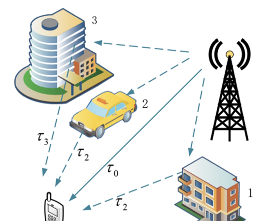
1.4 Daudzceļu izplatīšanās
Kad radioviļņi izplatās, papildus tiešajiem viļņiem tie tiek atstaroti, difraktēti un pārraidīti, saskaroties ar šķēršļiem, piemēram, pakalniem, mežiem un ēkām, kā rezultātā uztverošā termināla vienlaicīgi uztver daudzceļu radioviļņus — parādība, kas pazīstama kā **daudzceļu izplatīšanās**. Tās galvenā ietekme ir šāda: (1) signāla stipruma sadalījuma sarežģīšana, izraisot "ēnu izbalēšanu" un "strauju izbalēšanu", kā rezultātā rodas ievērojamas signāla stipruma svārstības uztveršanas galā; (2) radioviļņa polarizācijas virziena maiņa, kā rezultātā rodas polarizācijas neatbilstība un samazinās uztvertā signāla stiprums; (3) aizkaves izkliedes (laika starpības starp signāliem, kas pienāk pa dažādiem ceļiem) radīšana, izraisot starpsimbolu traucējumus; (4) lokāla signāla superpozīcijas (uzlabošanās) vai dzēšanas (vājināšanās atkarībā no ceļa starpības un viļņa garuma attiecības) izraisīšana. Piemēram, blīvi apdzīvotās pilsētu teritorijās ēku atstarojumi rada lielu skaitu daudzceļu signālu, kā rezultātā rodas biežas mobilo tālruņu uztvertā signāla stipruma svārstības.
Šīs problēmas galvenais risinājums ir **dažādības uztveršanas tehnoloģija**, kas uztver un apvieno daudzceļu signālus, lai mazinātu traucējumus. Tā ir iedalīta divās kategorijās:
1. **Telpiskā daudzveidība**: Izmanto vairākas vienpolarizētas antenas ar saprātīgu telpisko izkārtojumu (atstatums vairāk nekā 10 reizes lielāks par viļņa garumu), lai uztvertu signālus pa dažādiem ceļiem. Piemērots situācijām ar zemām polarizācijas prasībām.
2. **Polarizācijas dažādība**: Izmanto divkārši polarizētu antenu ortogonālās īpašības, lai vienlaikus uztvertu divus vertikāli polarizētus signālus (piemēram, +45°/-45°). Signālu zemās korelācijas dēļ apvienotā izeja ievērojami uzlabo uztveršanas uzticamību, padarot to par plaši pieejamu risinājumu pašreizējiem…
5G
bāzes stacijas.