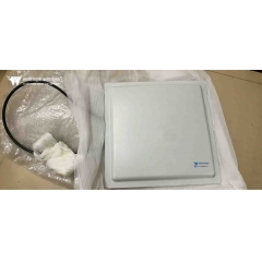

 WiFi maršrutētāja antena
Antenas polarizācija: kas tā ir un kāpēc tā ir svarīga
Paredzamais lasīšanas laiks: 15 minūtes
Katrs elektronikas inženieris zina, ka antenas pārraida un uztver signālus elektromagnētisko viļņu (elektromagnētiskās enerģijas viļņu) veidā, kuru īpašības var aprakstīt ar Maksvela vienādojumiem. Tāpat kā daudzus specializētus tehniskus tematus, arī šos vienādojumus kopā ar elektromagnētisko viļņu izplatīšanās noteikumiem un īpašībām var interpretēt no vairākām perspektīvām — sākot no salīdzinoši vienkāršiem kvalitatīviem aprakstiem līdz sarežģītām, detalizētām matemātiskām formulām.
Polarizācija ir viena no daudzajām elektromagnētiskās enerģijas izplatīšanās īpašībām. Tās ietekme un tas, cik lielā mērā tā jāņem vērā, dažādos pielietojuma scenārijos un atbilstošos antenu projektējumos ievērojami atšķiras. Polarizācijas pamatprincipi attiecas uz visu elektromagnētisko starojumu, tostarp radiofrekvences (RF)/bezvadu signāliem un gaismas viļņu enerģiju, un polarizāciju plaši izmanto optikas jomā. Šis raksts aptver tikai RF frekvenču joslu.
Kas ir antenas polarizācija?
Lai izprastu polarizāciju, vispirms jāapgūst elektromagnētisko viļņu pamati. Elektromagnētiskais vilnis sastāv no elektriskā lauka (E lauks) un magnētiskā lauka (H lauks), kas pārvietojas vienā virzienā. Elektriskais un magnētiskais lauks ir savstarpēji perpendikulāri, un abi ir perpendikulāri plaknes viļņa izplatīšanās virzienam.
Polarizācija tiek definēta kā elektriskā lauka vibrācijas plakne, skatoties no pārraides gala viļņa izplatīšanās virzienā. Horizontālās polarizācijas gadījumā elektriskais lauks svārstās no vienas puses uz otru horizontālajā plaknē; vertikālās polarizācijas gadījumā elektriskais lauks vibrē uz augšu un uz leju vertikālajā plaknē (skatīt 1. attēlu).

1. attēls: Elektromagnētiskais vilnis ar savstarpēji perpendikulāriem elektriskā un magnētiskā lauka komponentiem
Pārraides un uztveršanas antenas veido antenu pāri, un raiduztvērēja veiktspēja sasniedz maksimumu, kad abām ir identiskas polarizācijas plaknes. Atsaucoties uz ikonisko frāzi no 1979. gada filmas Alien — “Kosmosā neviens nevar dzirdēt jūsu kliedzienu” — ārējā kosmosā nav būtiskas atšķirības starp horizontālo un vertikālo polarizāciju. Tomēr polarizācijas saskaņošanas un antenu izlīdzināšanas teorijas joprojām ir spēkā, lai maksimāli palielinātu signāla enerģijas pārraidi un uztveršanu.
Lineārā un cirkulārā polarizācija
Elektromagnētiskajiem viļņiem ir vairāki polarizācijas režīmi:
- Pamata lineārā polarizācija ietver divas savstarpēji ortogonālas (perpendikulāras) polarizācijas formas (skatīt 2. attēlu). Teorētiski horizontāli polarizēta uztveršanas antena nevar uztvert nekādu signālu, ko izstaro vertikāli polarizēta pārraides antena, kas darbojas tajā pašā frekvencē, un otrādi. Jo tuvākas ir abu antenu polarizācijas orientācijas, jo spēcīgāks ir uztvertais signāls; signāla enerģijas pārneses efektivitāte sasniedz maksimumu, kad polarizācija ir pilnībā saskaņota.

2. attēls: Lineārā polarizācija piedāvā divas savstarpēji ortogonālas polarizācijas formas
- Slīpā polarizācija ir lineārās polarizācijas variants. Tāpat kā standarta horizontālā un vertikālā polarizācija, šī definīcija attiecas tikai uz uz zemes balstītiem scenārijiem. Slīpā polarizācija veido ±45° leņķi attiecībā pret horizontālo plakni. Lai gan slīpā polarizācija pēc būtības ir lineāra, kad nozares profesionāļi atsaucas uz “lineāro polarizāciju”, viņi parasti domā tikai horizontālās vai vertikālās polarizācijas antenas.
- Signālus, ko izstaro vai uztver slīpās polarizācijas antenas, var uztvert arī tikai horizontāli vai vertikāli polarizētas antenas, tomēr ar noteiktu signāla zudumu. Slīpās polarizācijas antenas ir ideāli piemērotas gadījumiem, kad vienas vai abu antenu polarizācijas stāvoklis nav zināms vai polarizācija darbības laikā mainās.
- Cirkulārā polarizācija (CP) ir sarežģītāka nekā lineārā polarizācija. Šajā polarizācijas režīmā elektriskā lauka vektors nepārtraukti rotē signāla izplatīšanās laikā. Skatoties uz āru no pārraides gala, elektriskā lauka vektora rotāciju pulksteņrādītāja virzienā sauc par labās rokas cirkulāro polarizāciju (RHCP); rotāciju pretēji pulksteņrādītāja virzienam sauc par kreisās rokas cirkulāro polarizāciju (LHCP) (skatīt 3. attēlu).

3. attēls: Cirkulāri polarizētu elektromagnētisko viļņu elektriskā lauka vektors rotē, sadaloties labās rokas un kreisās rokas tipos
Cirkulāri polarizēti signāli veidojas, pārklājot divus ortogonālus elektromagnētiskos viļņus ar 90° fāzes nobīdi. Lai izveidotu cirkulāro polarizāciju, jāizpilda trīs kritēriji: elektriskajam laukam jāietver divi ortogonāli komponenti; abiem komponentiem jābūt ar 90° fāzes starpību; un abiem komponentiem jābūt ar vienādu amplitūdu. Spirālveida antenas nodrošina vienkāršu risinājumu cirkulāri polarizētu viļņu ģenerēšanai.
- Eliptiskā polarizācija (EP) ir cirkulārās polarizācijas atvasinājums. Tāpat kā cirkulāri polarizēti viļņi, arī eliptiski polarizēti viļņi tiek sintezēti no diviem lineāri polarizētiem viļņiem. Eliptiskā polarizācija veidojas, kad tiek pārklāti divi savstarpēji perpendikulāri lineāri polarizēti viļņi ar nevienādu amplitūdu.
Polarizācijas neatbilstības pakāpi starp divām antenām kvantitatīvi nosaka ar polarizācijas zuduma koeficientu (PLF), ko mēra decibelos (dB). Tā vērtību nosaka polarizācijas leņķis starp pārraides un uztveršanas antenām. Teorētiski PLF ir vienāds ar 0 dB ideālas polarizācijas saskaņošanas gadījumā (nulles zudums); ja abas antenas ir pilnībā ortogonāli polarizētas, PLF tuvojas bezgalībai (pilnīga signāla vājināšana).
Tomēr reālās lietojumprogrammās antenas nevar sasniegt pilnīgi saskaņotu vai pilnībā ortogonālu polarizāciju. Mehāniska uzstādīšanas neprecizitāte, cilvēku darbības kļūdas, kanāla kropļojumi, daudzceļu atstarošanās un citi faktori ievieš leņķisku novirzi pārraidītā elektriskā lauka polarizācijas virzienā. Pat ja divas antenas ir paredzētas ortogonālai polarizācijai, praksē joprojām notiek šķērspolarizācijas noplūde 10 līdz 30 dB vai lielākā apmērā. Dažos scenārijos šis noplūdušais signāls ir pietiekami spēcīgs, lai traucētu vēlamā signāla demodulāciju.
Savukārt pat ar ideālu polarizāciju un precīzu divu antenu izlīdzināšanu reālās vides faktori var palielināt PLF līdz 10 dB, 20 dB vai vairāk, pasliktinot signāla uztveršanu. Vienkārši sakot, neparedzēta šķērspolarizācija un augsti polarizācijas zuduma koeficienti rada divas nelabvēlīgas sekas: tie ievieš traucējošus signālus un vājina mērķa lietderīgā signāla stiprumu.
Kāpēc polarizācijas īpašības ir svarīgas
Polarizācija pakļaujas divvirzienu noteikumam: jo ciešāk saskaņoti un konsekventi ir divu antenu polarizācijas tipi, jo augstāks ir uztvertā signāla stiprums. Turpretī slikta polarizācijas saskaņošana apgrūtina gan mērķa uztvērējiem, gan traucējumu uztvērējiem pietiekami spēcīgu izmantojamu signālu uztveršanu. Lielākajā daļā scenāriju bezvadu kanāls maina pārraidītā signāla polarizācijas stāvokli vai arī viens vai abi raiduztvērēji nespēj saglabāt fiksētu, nekustīgu antenas orientāciju.
Polarizācijas režīma izvēli parasti nosaka uzstādīšanas vide un atmosfēras izplatīšanās apstākļi. Piemēram, horizontāli polarizētas antenas nodrošina labāku signāla veiktspēju un stabilāku polarizāciju, ja tās uzstādītas pie griestiem; savukārt vertikāli polarizētām antenām, kas uzstādītas pie sānu sienām, polarizācijas uzvedība ir tuvāka to nominālajām projektēšanas specifikācijām.
Parastās dipola antenas (standarta dipoli / salocītie dipoli) tradicionālā uzstādījumā darbojas horizontālā polarizācijā (skatīt 4. attēlu). Ja nepieciešams pielāgot konkrētam polarizācijas režīmam, antenu var pagriezt par 90°, lai pārslēgtos uz vertikālo polarizāciju (skatīt 5. attēlu).
SHAPE \* MERGEFORMAT
4. attēls: Dipola antenas parasti tiek uzstādītas horizontāli uz mastiem horizontālās polarizācijas nodrošināšanai
SHAPE \* MERGEFORMAT
5. attēls: dipola antenas var uzstādīt vertikāli uz mastiem vertikālai polarizācijai, ja to pieprasa lietojumprogramma
Vertikālā polarizācija tiek plaši izmantota rokas rācijās, piemēram, ierīcēs, ko nēsā avārijas glābšanas personāls. Tas ir tāpēc, ka lielākajai daļai vertikāli polarizētu radioantenu ir visvirziena starojuma diagrammas — tas nozīmē, ka lietotājiem nav jāpielāgo antenas azimuts pat tad, ja rokas ierīces orientācija pastāvīgi mainās.
Lielākā daļa antenu kas darbojas augstfrekvences (HF) joslā no 3–30 MHz, izmanto vienkāršas garvadu antenu konstrukcijas, kas horizontāli izstieptas starp balstiem. To lielo fizisko izmēru nosaka atbilstošais viļņa garums (10–100 metri), un šādas antenas pēc būtības ir horizontāli polarizētas.
Interesanti, ka josla tika nosaukta par “augstfrekvences” joslu pirms vairākiem gadu desmitiem, kad 30 MHz tika uzskatīts par augstas frekvences diapazonu. Lai gan šis apzīmējums mūsdienās šķiet novecojis, tas joprojām ir oficiālais joslas apzīmējums, ko noteikusi Starptautiskā Telekomunikāciju savienība (ITU), un to joprojām visā pasaulē izmanto.
Vidējo viļņu (MW) josla aptver 300 kHz līdz 3 MHz. Šajā joslā apraides staciju izvēlētā polarizācija ir atkarīga no tā, vai stacija izmanto zemes viļņus īsa darbības attāluma spēcīga signāla pārklājumam vai jonosfēras telpas viļņus tālsatiksmes pārraidei. Kopumā vertikāli polarizētas antenas nodrošina labāku zemes viļņu izplatīšanos, savukārt horizontāli polarizētas antenas ir labāk piemērotas telpas viļņu sakariem.
Satelītsakari lielā mērā balstās uz cirkulāro polarizāciju. Satelīti pastāvīgi maina savu stāvokli attiecībā pret zemes stacijām un citiem satelītiem. Signāla pārraides efektivitāte sasniedz maksimumu, kad gan raidīšanas, gan uztveršanas pusē tiek izmantotas cirkulāri polarizētas antenas; lineāri polarizētu antenu savienošana ar cirkulāri polarizētām antenām darbojas, bet rada izmērāmu polarizācijas zuduma koeficientu.
Polarizācijas raksturlielumi ir vienlīdz būtiski 5G sistēmām. Daži 5G vairākievadu vairākizvadu (MIMO) antenu masīvi izmanto polarizācijas tehnoloģiju, lai efektīvāk izmantotu spektra resursus, palielinot caurlaidspējas ātrumu. Tas tiek panākts, apvienojot dažādus signālu polarizācijas režīmus ar antenu telpisko multipleksēšanu (telpisko daudzveidību). Šādas sistēmas vienlaikus pārraida divas neatkarīgas datu plūsmas, katru plūsmu padodot atsevišķām antenām ar savstarpēji ortogonālu polarizāciju, ļaujot uztvērējam demodulēt abas plūsmas atsevišķi. Lai gan neideāli faktori, tostarp izplatīšanās ceļi, kanāla kropļojumi, atstarošanās un daudzu ceļu efekti, rada nelielus šķērspolarizācijas traucējumus, uztvērēji tos iekšēji samazina.
Secinājums
Polarizācija ir būtiska, tomēr bieži vien nepamanīta antenu īpašība. Lineārā polarizācija (ieskaitot horizontālos un vertikālos variantus), slīpā polarizācija, cirkulārā polarizācija un eliptiskā polarizācija katra ir piemērota atšķirīgiem lietojuma scenārijiem. Antenu relatīvā orientācija un saskaņošanas pakāpe raidīšanas un uztveršanas galos tieši nosaka visa RF savienojuma kopējo veiktspēju. Komerciāli ir pieejams plašs standarta antenu klāsts, kas aptver visus polarizācijas tipus un RF frekvenču diapazonus, lai nodrošinātu polarizācijas risinājumus, kas pielāgoti visām mērķa lietojumprogrammām.